Solution
Application of Regenerative Braking Energy Inverter in Qingdao Subway
1 Introduction
DC traction power supplies used in urban rail transit systems often employ diode rectifiers with which electricity can only flow from AC network to DC traction network. The excessive regenerative braking energy generated when a locomotive brakes causes grid voltage to increase. The conventional solution to this problem is braking resistor, which, however, both wastes a lot of electricity and brings about temperature rise and other problems. Frequency starts and stops of locomotives produce a considerable amount of braking energy, which, if properly used, can lead to good economic benefit.
Two braking methods are mainly used nowadays. The first is mechanical braking (kinetic energy transformed to heat) whose weaknesses include friction contact surfaces are easily worn out, high temperature caused by friction may melt or burn contact surfaces, and dusts generated in friction cause pollution. The second is electrical braking which transforms kinetic energy to electricity, which is then either sent back to grid or again transformed to heat for consumption. Resistors are widely used in existing electric braking systems to absorb energy. Resistors can only transform electricity to heat, causing energy waste and temperature rise, which requires additional ventilation devices, which, in turn, need electricity consumption.
Another absorbing device for electric braking is capacitor-based storage type. Braking energy is absorbed into large capacity capacitor bank. Electricity stored there is discharged to locomotives within the power supply scope, which need electricity. Major weakness for this device are the need for a large size capacitor bank and capacitors cannot be used for a long time due to frequent charging and discharging cycles.
The third device used in electric braking is flywheel energy storage. When a locomotive brakes, the motor drives rotor to rotate for storing the regenerative energy until rotor reaches the highest speed; when the locomotive needs energy, motor is switched to generator state and then discharges the energy stored in rotor until rotor reaches the lowest speed; then the motor provides energy as a substation. The weaknesses include flywheel (rotor) life is dramatically reduced due to wear of mechanical parts and the investment and maintenance cost are high.
The fourth device used for electric braking is inverter, which inverters the energy generated in braking process to industrial frequency AC power, which is then connected to station grid. This mode is increasingly underscored and promoted because it can reuse and save energy in a comprehensive way.
2 WindSun Regenerative Braking Energy Inverter
The traction power supplies for rain transit systems are in locomotive traction substations, which, are arranged at an interval of 1 to 2 kilometers. Each traction substation needs devices to absorb regenerative braking energy.
Regenerative braking energy inverter (hereinafter referred to “inverter”) is a new generation device to process regenerative braking energy, in the response to green operation of trail transit locomotives, developed by WindSun. This inverter adopts inverter feedback control. From signals detected by sensors, the inverter decides if there are locomotives connected to the DC network which are producing regenerative braking energy. If so and when excessive energy must be absorbed, the system starts absorption process. The inverter transforms braking energy into AC400V power, tracts the voltage of AC400V bus, and provides power for loads, a way that consumes the regenerative energy on electricity consumption equipment; or it sends the AC400V power back to 35KV/10V grid through an isolation transformer. In a DC traction power supply system, the absorption device is a sub-system that is critical for system safety.
Compared with previous devices, this inverter provides fast dynamic response, small harmonic current for grid connect (THD <3%), high feedback efficiency (>98%) and high reliability. Tests performed by National Quality Test Center for Railway Products indicate that the product meets all designed requirements.
2.1 System framework
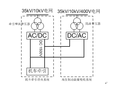
System framework presented in a box diagram is shown in Figure 1. Most traction substations for urban rail transit systems use 35KV or 10KV grids, which, are subject to traction rectifier transformers and 12-pulse reciters, output DC1500V or DC750V to locomotives.
Regenerative braking energy absorption device is connected to 1500/750V DC system in parallel. The energy is inverted to AC and sent back to grid (35KV/10KV/400V).

Figure 1 System framework diagram
2.2 Main circuit topology of the inverter
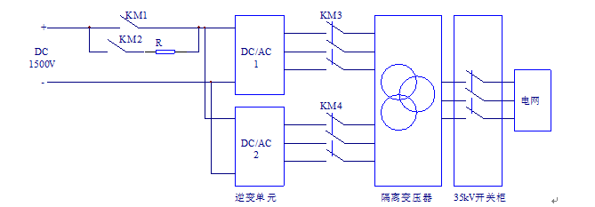
The inverter is chiefly comprised of input/output switches, inverter units, an isolation transformer and a switch-gear

Figure 2 Inverter box diagram
(1) Input/output switches
They are input DC contacts and output AC contacts for switching on and off of input and output of the inverter.
(2) Inverter units
An inverter unit is primary used to inverter energy accumulated from many instantaneous braking cycles to AC power which is synchronized with grid voltage and sends it back to grid. Existing traction power supply voltages are often DC750V and DC1500V. The main circuit is a diode-clamping three-level topology, as shown in Figure 3.

Figure 3 Main circuit topology of an inverter unit
(3) Isolation transformer
Inverter units output AC1000V/500V, which passes through the isolation transformer, and is connected to 35KV/10KV/400V grid.
(4) Switch-gear
Inverter unit output is connected to 35KV/10KV/400V grid through the isolation transformer
2.3 Technical features
(1) Leading control technology
The control system consists of DSP+FPGA/CPLD+PLC. Its automatic data collection function is used to collect internal state signals. MODBUS data transmission and interfaces with host system are supported. All state signals are provided.
(2) three-level topology for the main circuit
This circuit lowers voltage resistance requirement and helps reduce harmonic current at grid side.
(3) Easy capacity extension
Grid side of the control system is a current-source type that is easy for parallel connection and capacity extension.
(4) High power factor
Power factor at grid side is adjustable and the inverter can operate at unity power factor.
(5)Low harmonics
Grid side current is a sine waveform whose total harmonics distortion is smaller than 3%.
(6) Fast response, high efficiency
It provides fast dynamic response, being able to output rated current within several milliseconds; the device efficiency is higher than 98%.
(7) Complete protections
The inverter provides many protections against over-voltage, under-voltage, voltage imbalance, over-current, short circuit and over-temperature. When one inverter unit fails, the entire device can continue working with lowered parameters, which, does not affect locomotive operation.
3 Application
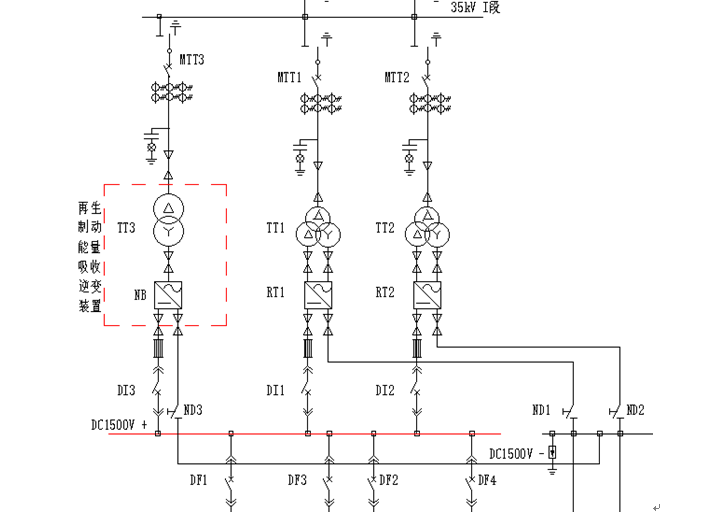
A subway traction power supply system in Qingdao comprises a DC traction network and an AC distribution grid. The connected subway power supply system is indicated in Figure 4. Main substation sends three phase 35KV high voltage AC power to all traction substations. The power is transformed to 1500V DC bus, which is suitable to rail transit trains, through rectifier transformers and reciters. Feed lines send the DC power to overhead contact system, which is a special power supply system constructed along the running rail. Trains receive electricity through the direct contact between their own collectors and the overhead contact system.
Each traction substation has two rectifiers, i.e., RT1 and RT2, in parallel. Each rectifier is a 12-pulse rectifying circuit, and two makes a 24-pulse rectifying circuit. Rated power, rated input current, rated output voltage, rated output current and permissible current fluctuation of each substation are respective 2400KW, 1180V, 1500V, 1600A and 1000V~1800V. Running rail forms a part of the traction power supply circuit. A return line works to send current flowing from tracks to traction substation. AC power distribution grid is an infrastructure that supports lighting, ventilation, water drainage and elevators in a station.

Figure 4 Subway power supply system wiring diagram
A WindSun device for absorbing and inverting regenerative braking energy (model FDBL-JC-2000/1500V), whose capacity is 2000KW, is installed in a station along the subway and is marked by a dash box in the above figure.
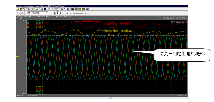
The device was put into production in early October, 2016 and has been operating soundly since then. DC bus current and inverted three-phase current waveforms of the device measured on site are given in Figure 5.

Figure 5 Waveforms of DC bus current and inverted three-phase output current
According to data measured by owner’s electricity meter, about 3000 kilowatt-hours are fed back each day. Assuming the industrial electricity price is ¥1.00 per kilowatt-hour, the station saves about ¥ 3,000 each year from the operating cost, indicating the significant energy saving effect. Furthermore, the device lowers requirements for ventilation and heat dissipation within tunnels. Stations are arranged at an interval of 1-2 kilometers averagely. If each station uses such device, the total operating cost for subway will be reduced greatly.
4 Conclusion
WindSun regenerative braking energy inverter control the operating voltage when locomotives brakes and ensure safety of trains. Obvious energy saving effect attributed to the device proves its compliance of energy saving and emission reduction policies. It can also lower ventilation and heat dissipation requirements for tunnels in which trains are driven and improves the operating environment for relevant equipment. As energy saving, environmental protection and green building are increasingly deepened in the “13th five year plan” period, this device is promising.