Solution
Application of Regenerative Braking Inverter in Nanjing Metro
1 Introduction
Traffic congestion is getting worse in large and middle Chinese cities, having become an important factor that restricts urban economic development. Attributed to its large capacity, fast speed, high safety and reliability, and punctuality and comfortableness, rail transit is undoubtedly an effective means to solve urban traffic congestion.
DC traction power supplies used in urban rail transit systems often employ diode rectifiers with which electricity can only flow from AC network to DC traction network. The excessive regenerative braking energy generated when a locomotive brakes causes grid voltage to increase. The conventional solution to this problem is braking resistor, which, however, both wastes a lot of electricity and brings about temperature rise and other problems. Frequency starts and stops of locomotives produce a considerable amount of braking energy, which, if properly used, can lead to good economic benefit.
From the earliest resistor-based energy consumption devices employed in traction substations to the capacitor-based energy storage devices and regenerative energy inverters developed in recent years, technologies for absorbing regenerative braking energy are in continuous development and improvement and have been applied in rail transit systems in China and abroad. Resistor-based energy consumption devices can only transform electricity to heat, which is then consumed, causing a huge waste; and heat dissipation from resistors will cause temperature rise, requiring appropriate ventilators, use of which will also increase electricity consumption. Capacitor-based energy storage devices absorb braking energy into large capacity capacitor bank, and release such energy when trains within its power supply range need such energy. The two main weakness are large size of capacitor banks and short useful life of capacitors due to frequent charging and discharging. Regenerative energy inverters change braking energy into an AC power at industrial frequency and connect such power to station grid, a way that can help comprehensive reuse of energy and is increasingly paid attention to and widely promoted.
WindSun regenerative braking energy inverters are inverter feedback type. The feedback energy is directly used to 400V loads in stations or sent back to the 10KV/35KV grid through transformers. From signals detected by sensors, the inverter decides if there are locomotives connected to the DC network which are producing regenerative braking energy. If so and when excessive energy must be absorbed, the system starts absorption process. The inverter transforms braking energy into AC400V power, tracts the voltage of AC400V bus, and provides power for loads, a way that consumes the regenerative energy on electricity consumption equipment, ensuring locomotives make the most use of electric braking. In a DC traction power supply system, the absorption device is a sub-system that is critical for system safety.
2 Traction Power Supply System in a Nanjing Metro Line
Nanjing Metro lines have their traction power supply systems located in locomotive traction substations which are arranged at an interval of 2 to 4 kilometers. Each traction system needs devices for absorbing regenerative braking energy.
Traction power supply system used for the rail transit line involved in this Metro line has two parts, i.e., a DC traction network and an AC electricity distribution grid. Main substation sends three phase 35KV high voltage AC power to all traction substations. Through a rectifier transformer and a rectifier, the power is transformed to 1500V DC bus which is suitable to rail transit trains. Feed lines send the DC power to overhead contact system, which is a special power supply system constructed along the running rail. Trains receive electricity through the direct contact between their own collectors and the overhead contact system.
Main electric parameters of the power supply system in this project are provided in Table 1.
Table 1 Main technical conditions and parameters of the system | |
System nominal voltage: | DC1500V |
System maximum continuous voltage: | DC2000V |
System minimum continuous voltage: | DC1000V |
Zero-load voltage at DC side | DC1650V |
Maximum voltage at regenerative braking | DC1980V |
System grounding method: | No grounding |
Traction transformer capacity | 2000kVA |
Distribution transformer capacity | 630kVA |
3 Description of WindSun FDBL-JC-650/1500V Regenerative Braking Energy Inverter
Regenerative braking energy inverter is independently developed by WindSun Science & Technology, which owns all the intellectual property rights therein. WindSun makes great efforts into multi-level topology technology used for inverters, current source control technology for voltage-type inverter, multi-unit parallel technology and grid connection technology, making a lot of breakthroughs. It took the lead in these technologies and successfully applied them in rail transit industry, filling an industrial gap in China. Development and application of key technologies in this project meets low carbon and energy saving requirements for urban rail transit systems and bolsters quality improvement and efficiency increase of home-made trail transit equipment.
This inverter provides fast dynamic response, small harmonic current at grid connection point, high feedback efficiency and great reliability. Tests performed by National Quality Test Center for Railway Products indicate that the product meets all designed requirements. It was included into 2014 National Torch Plan by the Ministry of Science and Technology and the Shandong List of First Assemblies in Key Sectors.
3.1 Main technical parameters of model FDBL-JC-650/1500V
Following are the main technical parameters of model FDBL-JC-650/1500V:
(1) Power: peak power 650KV continues for 20 seconds in a 120-second cycle
(2) Working system: intermittent
(3) Start voltage: adjustable continuously between 1530V and 1980V
(4) Output voltage: AC1000V three-phase three-wire system
(5) Frequency: follow AC grid frequency
(6) Output power factor at rated working condition: >0.98
(7) Device efficiency at rated working condition: >97%
(8) Harmonic current at rated working condition: ≤3%
(9) Harmonic voltage at rated working condition: ≤3%
(10) Response time: ≤ 200ms
3.2 Working principles
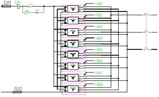
The inverter part consists of several units connected in parallel. Inverter output power is adjusted in response to DC bus voltage at regenerative braking. DC bus voltage is kept within a preset range. In this way, the entire device presents a current-source characteristic.
The inverter part mainly comprises DC contacts, inverter units, filter reactors and AC contacts as shown in Figure 1 to provide automatic start, stop, filter and detection functions.

Figure 1 Main circuit topology of the device
The device inverts the part of regenerative braking energy that is not consumed by other locomotives or other equipment to an AC voltage whose frequency and phase are identical to the grid voltage by adjusting output current of inverter unit according to changes in DC bus voltage, and sends this inverted AC voltage to the grid.
The main circuit play a key role in inverting and absorbing, automatic grid connection and inverting current regulation. It consists of many independent inverter units and control units. Each inverter unit has an IGBT as its switch and each control unit controls the switching on or off of each branch IGBT through PWM regulation. Actual capacity of regenerative braking energy is taken into account for adjusting the grid connection current. Protections against over-voltage, over-current, temperature rise and short circuit are provided.
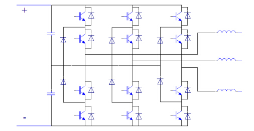
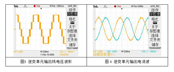
Each inverter unit is a three-level topology as shown in Figure 2. Output voltage waveform and output current waveform of the device are depicted in Figure 3 and Figure 4.

Figure 2 Power unit topology

Figure3 Output line voltage waveform of each inverter unit Figure 4 Output current waveform of each inverter unit
3.3 Display setting
3.4 Communication function
Standard RS485 port and the generally used and open Modbus protocol are used in control system, which can tele-signal switch position signals and failure signals, tele-meter amperes, volts and kilowatt-hours, and tele-control AC/DC contacts (if required). Fault information send by the control system to substation are labeled with time. Timing synchronization function is available between the control system and the used comprehensive automatic system.
3.5 Automatic data collection and storage
Control system can collect and store data and provide display and control pages. Locally collected data include: collection date and time, DC grid voltage, output AC voltage and current of inverter and feedback power. Processed by data collection system, these data area stored in local device and can also be transferred to other locations through USBs.
Operating state information, including switch state and system failure signals, is processed and displayed by control system. Switch sates include these in AC and AC switch-gear and inverter cabinet. Failure signals cover AC and DC grid voltage exceptions, power module exceptions, transformer exceptions and so on.
3.6 Protections
Built in the device are protections against AC grid under-voltage and over-voltage, DC grid under-voltage an over-voltage, power module over-current and over-temperature, isolator switch (state), heat dissipation fan failure, transformer over-heating, etc.
4 Upgrade Effect
To lower Metro operation cost, having taken many investigations, Nanjing Metro management signed an agreement with WindSun Science & Technology Co., Ltd, with respect to use of FDBL-JC-650/1500 devices in a metro line. With close collaboration from two parties, a careful renovation plan was prepared. On January 8th, 2015, the renovation project was completed. Inverters were put into production successfully and have been operating since then, having showed great effect of saving energy and met expected renovation objective.
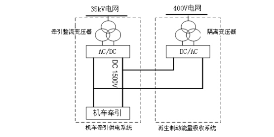
This model feeds absorbed regenerative braking energy into a 400V grid for use by other equipment in the metro. The box diagram presenting connection of this model into the metro grid system is shown in Figure 5.

Figure 5 System framework diagram
To measure how much energy would be saved, Nanjing Metro installed kilowatt-hour meters to measure electricity fed back and its effect. Measurements over the past one year indicate that about 1000 kilowatt-hours has been saved per day, amounting to 365,000 kilowatt-hours per year after this device was put into service. This means, at the local electricity price of 0.8451/kilowatt-hour, about ¥308,000 would be saved a year. In addition, use of this device spares the electricity originally needed by tunnel heat dissipation when resistor-based devices were utilized and means another considerable amount of saving.
5 Conclusion
Regenerative braking energy inverters developed by WindSun have been successfully used in metros in Beijing, Chongqing, Tianjin, Nanjing and other cities, being the earliest applied and most reliable product that provides the most outstanding performance for metro application. As people are more aware of the important of environment protection and energy saving, inverter-based devices for absorbing regenerative braking energy will be accepted by more metro corporations and this product will be universally used in metros.