Solution
Application of Regenerative Braking Energy Inverter in Chongqing Metro
1 Introduction
Attributed to its large capacity, fast speed, high safety and reliability, and punctuality and conformability, rail transit is increasingly becoming a major urban transportation and regarded as the backbone of urban transportation system. DC-AC variable voltage variable frequency technology is generally used in urban rail transit systems where locomotives brake “electrically (regenerative braking) and mechanically”; Electric braking is primary while mechanical braking plays a supporting role. Short inter-station distance results in frequency starts and stops of locomotives, which therefore generate a considerable amount of energy. In China, resistors placed on ground are often used to absorb regenerative energy produced by locomotives, a way that not only wastes energy but also increase the burden of air-conditioning system within a station, and thereby increasing the cost of urban rail transit construction and operation. These problems can be easily removed f this energy is stored and then utilized.
Devices that absorb regenerative braking energy are classified into four types, resistor-based energy consumption type, capacitor-based energy storage type, flywheel-based energy storage type and inverter feedback type. Chongqing metro uses the first and the fourth types. In inverter feedback mode, the DC current generated by trains which are braking is inverted into AC power at industrial frequency, which is then connected to the 380V grid in the station. In this way, energy is consumed for elevators, lighting systems, ventilation systems and other electricity consumption facilities in the station. This solution is advantageous to comprehensive utilization of energy and energy saving.
2 Renovation Project in Chongqing Metro (Group) Co., Ltd.
2.1 Company profile
Founded in 1992, Chongqing Metro (Group) Co., Ltd is the only large state-owned-enterprise in the field of passenger rail services that provides integrated services, including constructing and operating rail transits and developing resources along these rails. The Group has over 10,000 employees and an asset of more than ¥70 billion, maintains Grade A qualification for rail transit design, Grade A qualification for project management, Grade A qualification for construction supervision, Grade A qualification for project consulting and Level 2 qualification for real estate development. It has developed many key technical staffs who are long-term engaged in technology research and construction management with respect to rail transit systems and an outstanding technology, operation and management team consisting of members that have received systemic training from large-sized metro companies both in China and abroad. It is able to plan urban, construct and operate urban rail transit systems as well as provide technical consulting services in connection therewith. It guarantees that Chongqing rail transit goals can be achieved by providing qualified technology and human resources.
The Group successfully constructed and is operating China’s first straddle monorail, that is, Chongqing No. 2 rain transit line. Total four lines in operation amounts to 170 kilometers in distance. By 2015, rail transit systems the Group completes will reach 208 kilometers; this figure will be increased to over 300 kilometers by 2020, transporting 6 million passengers per day.
2.2 Traction power supply system
Traction power supply system used for the rail transit line involved in this project has two parts, i.e., a DC traction network and an AC electricity distribution grid. Main substation sends three phase 35KV high voltage AC power to all traction substations. Through a rectifier transformer and a rectifier, the power is transformed to 1500V DC bus which is suitable to rail transit trains. Feed lines send the DC power to overhead contact system, which is a special power supply system constructed along the running rail. Trains receive electricity through the direct contact between their own collectors and the overhead contact system.
A traction substation generally has two traction rectifier units, which are connected in parallel, forming an equivalent 24-pulse rectifier circuit. Predicated passenger volume is the basis for capacity design. According to GB/T 10411-2005 D.C.traction power supply system for urban rail transit, a traction rectifier unit must be able to provide 100% of rated output continuously, 150% of rated output for 2 hours, 300% of rated output for 1 minute. Permissible voltage is from 1000V to 1800V. Running rail forms a part of the traction power supply circuit. A return line works to send current flowing from tracks to traction substation.
AC power distribution grid is an infrastructure that supports lighting, ventilation, water drainage and elevators in a station.
3 WindSun Regenerative Braking Energy Inverter
3.1 Overview
WindSun regenerative braking energy inverter (hereinafter referred to as “inverter”) is an inverter feedback type device, the energy sent back from which is used for a 400V load. From signals detected by sensors, the inverter (inverter+ resistor) decides if there are locomotives connected to the DC network which are producing regenerative braking energy. If so and when excessive energy must be absorbed, the system starts absorption process. Two-level thresholds are set in control system. When grid power rises up to the first level voltage threshold, system starts the inverter which transforms energy generated by locomotives which are braking to an AC380V voltage, automatically tracts voltage at AC380V bus and provides power for its load; in this way, the regenerative energy is used on electricity consumption equipment. Inverter’ inability to absorb and consume so much energy will result in further rise of grid voltage, when, which is increased to the second-level threshold, a resistor chopper immediately starts working; in this case, resistor-based absorption device consumes the regenerative braking energy to stabilize voltage, thereby ensuring locomotives make full use of electrical braking. In a DC traction power supply system, the absorption device is a sub-system that is critical for system safety.
3.2 Main circuit system
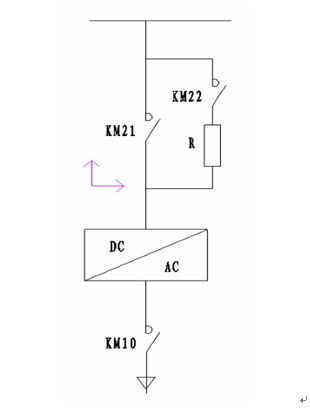
Primary main circuit of the inverter is chiefly comprised of DC contacts, inverter units, a filter reactor, AC contacts and other parts. The main circuit is depicted in Figure 1.

Figure 1 Schematic diagram of inverter’s main circuit
3.3 Electrical principles
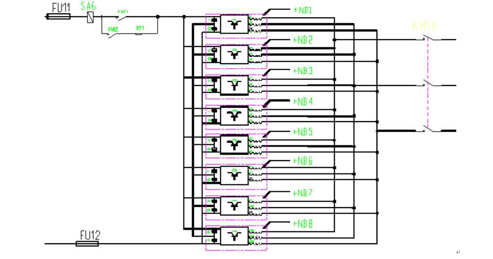
The inverter consists of many units that are connected in parallel. Due to high feedback power and low grid voltage, the total output current is fairly large, which means that a multi-unit parallel topology can better implement the structure. Figure 2 gaives the shcemiatic diagram of this topology.

Figure 2 Main circuit (a multi-unit parallel structure) diagram
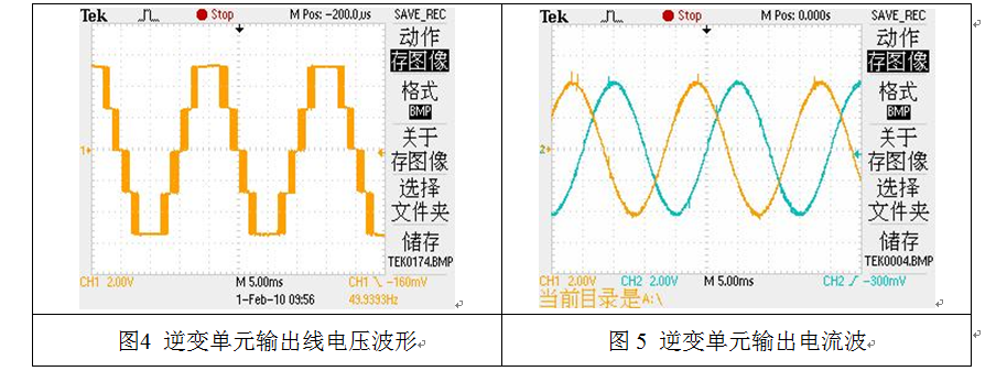
Each unit of the inverter is a three-level topology, as shown in Figure 3. Output voltage and output current waveforms of the inverter are displayed in Figure 4 and Figure 5 respectively.

Figure 3 Power unit topology

Figure 4 Output line waveform of an inverter unit Figure 5 Output current waveform of an inverter unit
3.4 Working principles
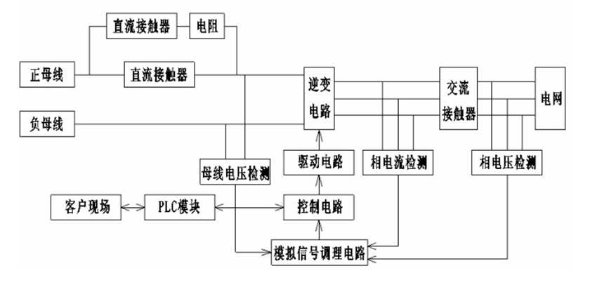
After receiving the start signal from master control, which means, the reactive normally-open point for start/exit signal is closed, this device sends out a signal that confirms starting operation is finished, i.e., this reactive normally-open point is closed, through the control circuit. Having detected the signal that confirms starting operation is finished, master control sends a start point signal determined by bus voltage amplitude. An IGBT for the point is immediately switched on to provide energy feedback. A working IGBT receives control signals from master control and provide working statue signals of contacts and units within the device for master control. Figure 6 shows the control diagram of the device.

Figure 6 Device control diagram
4 Operating Effect
The regenerative braking energy inverter has manifested great effect in energy saving, as shown in the following statistics (a Chongqing rail transit line).
Station name | Total kilowatt-hours | Average kilowatt-hours per day | Period | |
Shapingba | Last time | 943,067 | March 20, 2013 | |
Current month | 997,604 | April 28, 2013 | ||
Kilowatts-hours saved | 54,537 | 1,398 | 39 days | |
Xietaizi | Last time | 945,194 | March 20, 2013 | |
Current month | 1,001,528 | April 28, 2013 | ||
Kilowatts-hours saved | 56,334 | 1,444 | 39 days | |
Qixinggang | Last time | 674,827 | March 20, 2013 | |
Current month | 727,127 | April 28, 2013 | ||
Kilowatts-hours saved | 52,530 | 1,346 | 39 days | |
With Xietaizi inverter as an example, the inverter sends back1,444 kilowatt-hours per day, which means ¥ 1,444 is saved one day (industrial electricity price is ¥1.0/kilowatt-hour) and more than ¥520,000 a year. This device imposes lower requirements on lower ventilation and heat dissipation within tunnels, which lowers operating cost and presents a significant economic benefit.
5 Conclusion
China’s urban rail transit construction has moved into a rapid development phase. Although being a green transportation, urban rail transit, according to market investigation, has become a major urban electricity consumer that also consumes excessive energy. Regenerative braking energy inverters have demonstrated great energy saving effect in Chongqing rail transit systems and are stably operated in Line 1, Line 3 and Line 6. These inverters have obtained great economic and social benefits which are adapted to the great trend for constructing a society for saving resources.