Solution
Application of WindSun 35kV Direct Mounting SVG to A Photovoltaic Station
1 Project Introduction
The 50MW photovoltaic station in this project is located in Minqin County, Wuwei City, Gansu Province, about 67.5 kilometers away from Minqin County to its southeast, about 2.5 kilometers away from Hongshagang Town to its north and adjacent to No. 212 Province road to its west. The road introducing to the station is an eastward extension of No. 2012 Province road for about 200m.
With a total generation capacity of 50MWp and a 35KV voltage connected to the system, the photovoltaic station is a fixed flat-plate array comprising 212,784 polysilicon solar panels, each of which is 235W, an inverter, a 35KV step-up transformer and supporting equipment for, such as, relay protection, automation, optical power predication, communication, measurement and computer monitoring. The PV station’s designed annual capacity is 7747.4 kWh. The FGSVG-C12.0/35 high voltage dynamic reactive power compensation device produced by WindSun Science & Technology Co., Ltd. is utilized in this PV station for improving the station’s grid quality.
2 WindSun FGSVG-C12.0/35
This high voltage dynamic reactive power compensation device is described as below.
2.1 Technical parameters
The FGSVG-C12.0/35 used in the 50MW PV station in 12Mvar in total capacity, being able to output 12Mvar inductive or capacitive reactive power dynamically. By detecting the reactive power at the 35KV side, it dynamically compensates the system’s reactive power and controls harmonics, thereby controlling the voltage and power factor.
Technical parameters of WindSun FGSVG-C12.0/35 are listed in Table 1
Table 1 Technical parameters of FGSVG-C12.0/35 | ||
No. | Item | Technical parameter |
1 | Rated working voltage | 35kV |
2 | Rated capacity | -12.0~+12.0Mvar |
3 | Output reactive power | Continuous change from inductive to capacitive rated reactive power |
4 | Response time | ≤5ms |
5 | Over-load capacity | 1 minute for 1.2 times of the rated load |
6 | Output voltage THD (before grid connection) | ≤5% |
7 | Output current THD | ≤3% |
8 | System voltage imbalance protection and rectifying range | 4%~10% |
9 | Efficiency | ≥99.2% at rated working conditions |
10 | Operating temperature | -20℃~+40℃ |
11 | Storage temperature | -40℃~+65℃ |
12 | HMI | Color touch panel with display in Chinese |
13 | Relative humidity | Monthly average value is not higher than 90% (25℃) without condensation |
14 | Elevation | <1000 m (customize product for higher than 1000m) |
15 | Seismic intensity | ≤scale 8 |
2.2 FGSVG-C12.0/35 Characteristics
FGSVG is designed to meet user’s urgent needs for increasing power factor of electricity transmission and distribution grid, controlling harmonics and compensating negative sequence current by being highly reliable, easily operated and strongly functional. Its characteristics are listed as below:
(1) Modular-based design simplifies installation, commissioning and setting.
(2) Fast dynamic response with a response time ≤5ms.
(3) Output current’s total harmonics distortion ≤3% provided that sufficient compensation capacity is in place.
(4) Many operating modes, i.e., device reactive power mode, targeted point reactive power mode, targeted point power factor mode, targeted point voltage mode and targeted point reactive power mode 2, can meet diverse needs; with the target values can be modified in a real time manner.
(5) By tracking load changes, it dynamically and continuously compensates reactive power in a smooth manner, increases system’s power factor, suppresses harmonics and compensates negative sequence current, thereby improving the grid’s electricity quality.
(6) It can suppresses voltage flicker, improve voltage quality and stabilize system voltage.
(7) Carefully designed circuit parameters allow a small heat generation, a high efficiency and a low operating cost.
(8) Compact structure requires a small space for installation.
(9) The main circuit is a series of H bridge power units that comprise of IGBTs; each phase of the circuit consists of many identical power units; the final output is a square waveform, a superimposition of many PWM waveforms outputted by power units, which approximates a sine waveform; Filtered by a reactor, the output is almost a perfect sine waveform.
(10) Redundancy design and module design ensure the high reliability of system.
(11) Power circuit is a module-based design that ensures easy maintenance and good interchangeability.
(12) Complete protections, including over-voltage, under-voltage, over-current, unit over-heating, voltage imbalance, etc. and the ability to record failure waveform in order to help with failure point locating and easy maintenance, ensuring high operating reliability.
(13) Friendly HMI provides RS485 and other ports for external communication under standard Modbus protocol. Apart from real time displaying digital quantities and analog quantities, recording historical operating events, searching historical curves, monitoring unit states, searching system information and searching historical failures, the HMI also provide system self-test, one-key start/stop, time-shared control, oscilloscope (AD channel forced waveform recording), recording instantaneous voltage/current waveform in the event of failure
(14) FGSVG is designed with ports that match with FC to effectively combine static compensation and dynamic compensation, providing more cost effective and flexible solutions for users.
(15) No transient impulse, no surge and no arc restrike from switching, no discharge is required for switching again.
(16) AC phase sequence is not a factor that should be considered for connection to the system.
(17) Parallel installation is permitted for easy capacity extension. Ring fiber optical communication is used for many FGSVGs that operate in parallel to achieve fast communication that perfectly satisfy real time compensation requirement.
2.3 System structure
FGSVG’s main circuit is a chained topology, with a modular-based design and a star connection. Each phase is a series of 20 power units. The star connection is depicted in Figure 1.
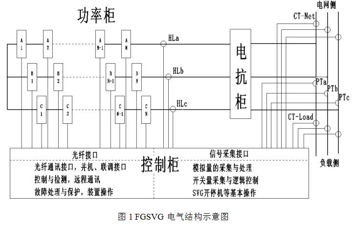
Figure 1 FGSVG’s Electric Structure Diagram
Signals of control cabinet and power cabinets are separated by fiber optic cables, a reliable way to separate high voltage from low voltage. Significant improvement in the structure of FGSVG series ensures the easier maintenance. Strict anti-interference protection is taken for the control cabinet to prevent the control system against high voltage main circuit. Power unit is improved so that it requires a smaller space, a way to reduce user's investment requirement.
An FGSVG is chiefly comprised of three parts: control-gear, power cabinet and reactor cabinet. The power cabinet is greatly standardized, which provides convenience for capacity extension and stability. FGSVG devices of different voltage levels consist of control cabinet, power cabinets and reactor cabinets (or air core reactors). Main components in each cabinet and their roles are listed in Table 2.
Table 2 Main Components and Their Roles | ||
Structure | Component | Role |
Control-gear | Switch | Switch on or off the main circuit |
Snubber | Suppress the voltage spikes on bus when the module is being charged. | |
Data Collector | Collect switching quantities and analog quantities | |
Control Box | Process data | |
Logic Controller | Logic control | |
Human-Machine Interface | Parameter setting and display as well as waveform recording | |
Secondary Power Source System | Power source processing for a stable control system | |
Power Cabinet | Power Unit | Voltage of certain amplitude and phase is cascaded according to signals |
Mandatory Air Cooling System | Forced cooling of the modular unit | |
Reactor Cabinet | Reactor |
Connection of reactive power source to the grid and current filtering |
2.3.1 Control-gear
The main circuit includes an isolator switch QS1, a breaker QF, a snubber resistor R, a status detector, etc., as depicted in Figure 2.
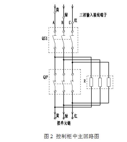
Figure 2 The Diagram of the Main Circuit in the Control-gear
The standard main control box independently developed by WindSun has passed the EMC certification under GB/T17626 and temperature shock and vibration tests, indicating its extremely high reliability.
The control core of the main control box is provided by the synergy computation between a 32-bit high speed digital signal processor (DSP) and a complex programmable logic device (CPLD)/FPGA. Carefully designed algorithm ensures the optimum operating performance of the FGSVG. Large scale integration based controller is manufactured with surface welding technology, ensuring system’s extreme high reliability. Siemens PLC increases system flexibility.
An emergency stop button is placed on the door to facilitate the user to operate in the case of emergency. As indicated in Figure 3, a friendly HMI from Weinview, a leading Chinese supplier who adopts world-class equipment and standardized operating procedures that are parallel in international standards to ensure its premium quality.
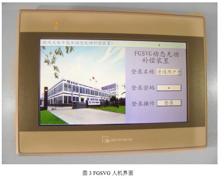
Figure 3 FGSVG HMI
2.3.2 Power cabinet
The power cabinet mainly contains a power part, forming the main part for FGSVG reactive power compensation. The power part in installed in three phases, each of which consists of 20 power units. The waveforms outputted by all power units are superimposed to form the output waveform of the device. Each power unit bears the entire output current, 1/20 of the phase voltage and 1/60 of the output power. The heat generated by each unit when it is working is dissipated by the fan designed on the top or back door of the cabinet.
Deliberately selected film DC capacitors are made from the PHD high temperature resistant PP film manufactured by Treofan Germany GmbH, guarantee product reliability.
Each power unit provides complete protections (over-current, over-voltage, over-heat, drive trigger exception and communication exception). Optical fiber communication is used between the controller and power units with completely and reliably separation of low voltage from high voltage. In this way, the system excels in safety and EMI immunity.
Modular-based design makes all power units share the same structure and ensures high interchangeability. Only two or four lead-out terminals and two optical fiber connectors are designed as external interfaces, a design that ensures easier maintenance and service. Each power unit provides sine PWM control through IGBT-based inverter bridge so that the unit output waveform shown in Figure 4 can be obtained.
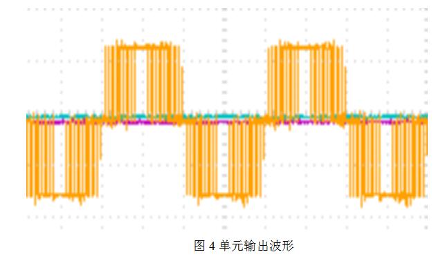
Figure 4 Unit Output Waveform
After each power unit is chained, three phases that are star or delta connected are then connected to the grid through reactors. Superimposition of all PWM waveforms from all units result in the square PWM waveform that is similar to a sine waveform. Figure 5 gives the waveform of a single phase from a star-connected device.
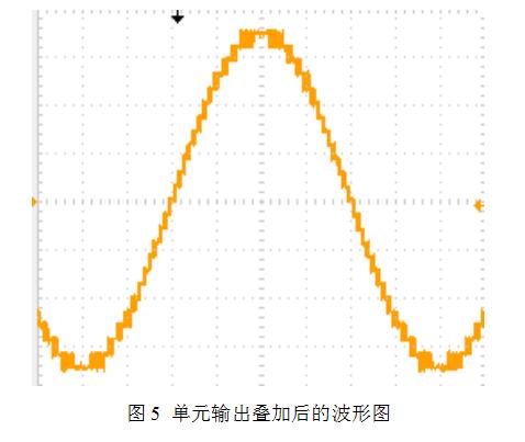
Figure 5 Waveform Superimposed from all Unit Outputs
FGSVG series is designed with the state-of-art Carrier Phase Shifting (CPS) technology with which, fundamental waves outputted by all units are superimposed, harmonic waves outputted by all units are offset, and waves from units in series are filtered by output reactors so that the total output has a good sine wave form with a small dv/dt and a small harmonic component, which can reduce the damage to cable insulation and save the necessity to add output filters at the output side.
2.3.3 Reactor cabinet
An FGSVG device is connected to the grid through a reactor L for better sine waveform current. While smoothing waves, the reactor also inhibits SVG harmonics so that the current harmonics outputted by the device complies with national standard. Split-designed reactor increases space utilization and mitigates the space limitation to the device, a way that also reduces investment.
2.4 FGSVG’s operating modes
Five operating modes are available: device reactive power mode, targeted point reactive power mode, targeted point power factor mode, targeted point voltage mode, targeted point reactive power mode 2, each of which can be selected in a pull-down list on the right of which the targeted value is set and may be modified at any time. The compensation effect after each change of the setting value can be examined based on the test value. "Operating modes" are detailed in the following Table 3.
Table 3 FGSVG Operating Modes | |
Operating Mode | Description |
device reactive power mode | The FGSVG sends or absorbs the reactive power of the set value. |
targeted point power factor mode | The FGSVG compensates the targeted point at the set power factor (-100%~+100%) within its compensation capacity. |
targeted point voltage mode | The FGSVG stabilizes grid voltage around the value set by the user by adjusting its reactive output. |
targeted point reactive power mode | The FGSVG stabilizes reactive power of the targeted point around the value set by the user by adjusting its reactive output. |
targeted point reactive power mode 2 | In this mode, the FGSVG adjusts its reactive power by detecting the reactive power of the load side so that the reactive power of the system side is kept at zero or around the set value. |
To achieve the communication between FGSVG device and its host, MODBUS_RTU protocol and CDT-91 protocol are adopted. Matured communication mode guarantees the safety and reliability of FGSVGs that operate in parallel, increases the tracking speed of slave devices and meets the demand for large capacity FGSVG's connection to the grid.
The HMI installed on the cabinet door provides tele-signaling and tele-metering verification regarding communication information when the device is not powered at high voltage in order to help the commissioning professionals test communication channels and data (Figure 6).
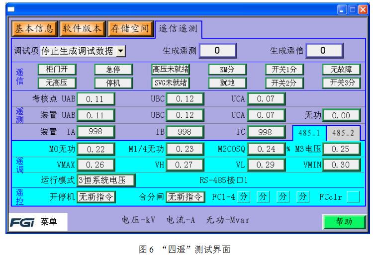
Figure 6 "Tele-signaling, Tele-metering, Tele-controlling and Tele-adjusting" Test Interface
“Commissioning item” is a pull down list where there are some options. Select one item and input the targeted value in the data box. If addresses match, host will display corresponding data/state or FGSVG will receive a control signal. As shown in Figure 6, the user selected tele-signaling quantity, and set the corresponding value toward which the tele-signaled quantity is adjusted. The “tele-signaling” column on the page means current set state. With normal communication and correct address of the host, the state will be displayed correctly, which means successful commissioning. Other items are commissioned in a similar way.
3 Application
The primary wiring diagram for the step-up transformer in the 500MW PV station is indicated in Figure 7.
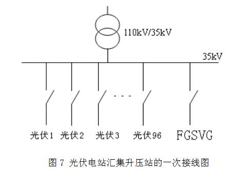
Figure 7 Primary Wiring Diagram for the Step-up Transformer in the PV Station
Government-controlled PV electricity price declines each year. The 50MW PV station was completed at the end of 2013 and started for production and connected to the grid on December 29, 2013; From then on, it received tests including charging a 110kv line, a 110kv switch breaker test and other switching tests, charging the main transformer, charging the PV branches of a 35kv line and FGSVG connection to the grid.
Through the PT and CT installed on 110kV side, FGSVG detects voltage and current at grid connection point, a way that can help device reactive power control, targeted point voltage control, targeted point reactive power control and targeted point power factor control. As required by dispatching, targeted point power factor mode is used in the project. It only took one try to successfully connect FGSVG to the grid and enable it to provide normal performance. After a 24-hour trial run, the PV station was transferred to normal operation, meeting the goal to start connection before forthcoming new year. This solution met the PV station’s requirement for reactive power compensation and passed the acceptance smoothly.
After put into service, the 50MW PV station has been keeping a stable power factor between 0.98 and 0.99, which meets both power generation demand and power factor requirement.
An SVG is able to filter harmonics. Harmonic current at the grid connection point after SVG was put into production has been kept below 2%. Compared with conventional reactive power compensation devices, SVG provides much higher response within 5 ms. It can suppress grid voltage dip and flicker. The waveform after grid connection is given in Figure 8.
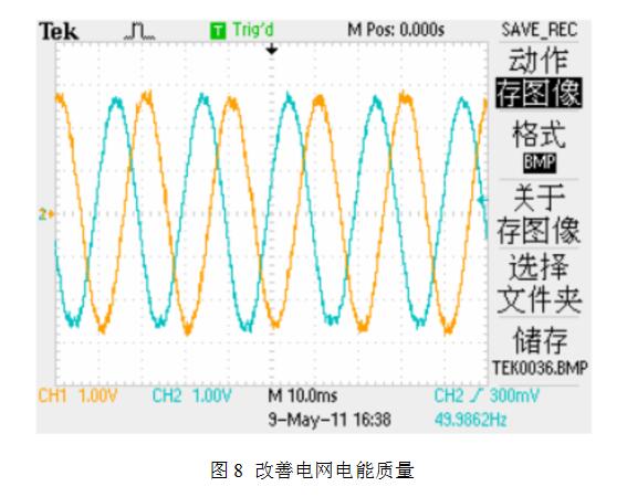
Figure 8. Grid Electricity Quality is Improved
Response speed waveform (Figure 9):
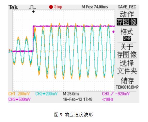
Figure 9 Response Speed Waveform
4 Conclusion
The 50MW PV station’s operation over the last two-some years indicates that FGSVG provides a stable and reliable performance in a highly automated way, improves grid quality and meets the expectation. This project has been highly though of by Gansu Grid Company. It is significantly advantageous over other existing reactive power compensation devices, presenting great value in wide application to PV stations.