Solution
Application of a 7MW High Voltage Variable Frequency Power Supply in Pump Test Stand
1 Introduction
Hunan Nanfang Changhe Pump Co., Ltd., a wholly-owned subsidiary of Nanfang Pump Industry Co., Ltd. and situated in Changsha Economic and Technological Development District, Hu'nan, is a base for sale, R&D, manufacturing and experimenting high-end middle and large-sized pumps, in Nanfang Pump Industry Co., Ltd.
The Company mainly produces single-stage double-suction middle-open centrifugal pumps, horizontal multi-stage centrifugal pumps, horizontal long-axis pumps, condensate pumps with barrel, vertical and submersible diagonal-flow pumps, vertical and submersible axial-flow pumps, volute casing mixed-flow pumps and sewage pumps, segmented casing multi-stage centrifugal pumps, right angle gearboxes for pumps, motors used for large and middle-sized water-cooling deep well pumps, various pumps used for membrane-based seawater desalination and petrochemical pumps such as API610, BB1, BB3, OH1, OH2, VS1, VS6 and VS7, Which are widely applied in electricity, metallurgy, steel, water resources, municipal facilities, environmental protection, dredge, petroleum, chemistry, firefighting and other fields. More than 70% of its products are exported to over sixty countries in Europe and Americas. These make it the company that produces the most complete range of middle-open pumps and long-axis pumps with the largest export.
2. Pump Test Center
The Pump Test Center in Hunan Nanfang Changhe Pump Co., Ltd., intended to upgrade its original variable-frequency power supply system by adopting full-automatic host monitoring system. The upgraded system can provide performance tests on various kinds of pumps and get the accurate data of shipped pumps and its R&D result.
Changhe Pump's technical parameters for original high voltage variable-frequency power supply system: input voltage 10 kV, output voltage 10 kV/6 kV, output current 0A -400 A, frequency adjustable within 0-75 Hz; for upgraded system: input voltage 10 kV, continuously variable output voltage within 1100V-10000 V, output current 0A -450 A, frequency adjustable within 0-75 Hz at any possible output voltage.
Automatic host monitoring system can monitor the entire test center. High-precision test instruments, sensors and computers work together to provide automatic measuring and monitoring, data collection, data processing, analysis of electrical parameters and fluid parameters, automatic display and printing of test results, plotting of characteristics curves (variable-speed, diameter, variable-angle) and analysis of system uncertainty. Data in the central control unit and the reception unit can be operated and displayed synchronously.
3. Basic Parameters of WindSun High-voltage Variable Frequency Power Supply Control System
WindSun high-voltage variable frequency power supply system is designed to be highly reliable, easily operated and highly functional. With new IGBT power components and full-digital microcomputer control, the system has its basic parameters as shown in Table 1.
Table 1. Basic parameters of WindSun high-voltage variable-frequency power supply | ||
No. | Name | Parameters |
1 | Type and model | High-high, JD-BP38-7000F |
2 | Technical plan | Multi-level series, voltage source, high-high approach |
3 | Input voltage (kV) | 10 |
4 | Output voltage (kV) | 0~10kV/6kV/3kV/2300V/1100V |
5 | Maximum output current (A) | 540 |
6 | Rated input frequency (frequency range) | 45-55Hz |
7 | Sensitivity to grid voltage fluctuation | Full-load output when the grid voltage is changes by +10%~-10%; continuous output lower than the rated output when grid voltage is decreased by up to 35%; the power system can be recovered and restarted within 3 seconds when the input voltage is decreased to be lower than 65%of the rated voltage or when the power is cut down suddenly. |
8 | Efficiency | >96% (at rated output, including the transformer) |
9 | Input side power factor | >0.96 (when the load is more than 20% of the rated value) |
10 | Control method | Multi-stage sine PWM control |
11 | Rectifying method | Diode full bridge rectifier |
12 | Inverter form | IGBT single-phase inverter |
13 | Over-load capacity | 1 minute for 120% of rated load and immediate protection for 150%of rated load |
14 | Specification and quantity for analog signal (input) channels | Standard industrial signals: 4~20mA 1 channel |
15 | Specification and quantity for analog signal (output) channels | Standard industrial signals: 4~20mA 2 channels |
16 | IP grade | IP31 |
17 | Operation keyboard | Human-machine interface |
18 | Interface language | Simplified Chinese |
4 High-voltage Variable Frequency Power Supply System
The WindSun high-voltage variable-frequency power supply system is designed to provide "high-high" transformation, with a multi-level unit series topology which means the main structure is a series of multiple power modules which produces many groups of low-voltage outputs. These low-voltage output are superimposed to form the required high-voltage output. This structure results in small harmonics contamination on the grid and a small input harmonic distortion, which complied with the harmonic suppression standard as specified in IEEE519-1992. High input power factor makes input harmonic filter and power factor compensation device unnecessary. The output wave presents a high quality and the output voltage's total harmonic distortion is less than 2%, free from additional heating of motor and torque pulse, noise, output dv/dt and common mode voltage problems caused by harmonics. In this way, no output filter required to go with conventional asynchronous motors.
4.1 Power System Topology
For an output of 0-10 kV, the power source system has 24 power units and each 8 units form a phase in series. The system structure is shown in Figure 1.
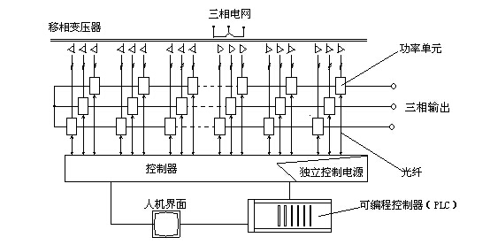
Figure 1 Structure of variable frequency power supply system
4.2 Power Unit
Each power unit is powered by a group of secondary sides of the input transformers. Each two power units and each two secondary coils are insulated. Secondary coils are connected in star-mode for multiplex purpose, thereby lowering the input harmonic current. All power units are structured identically and interchangeable. Each power unit is a basic single-phase inverter circuit whose rectifier side is a diode three-phase full bridge. IGBT inverter bridge is controlled by PWM and has automatic unit bypass function, which can greatly increase system reliability.
4.3 Power Cabinet
Power units are combined in the cabinet. U output terminal and V output terminal of each power unit is connected in series one by one to form the star-connection that can provide electricity for motors. The PWM waveform produced by each power unit are recombined to obtain the best PWM waveform with small dv/dt, a way that can reduce the damages to cable and motor insulations. This makes it possible to use long output cables without filters and use motors at their rated output.
4.4 Control-gear
The controller is equipped with a 32-bit high speed DSP chip and precise algorithms to ensure the optimum motor performance. Color-embedded human-machine interface provides friendly Chinese monitoring and operating pages with remote monitoring and networked control available. The controller has a built-in PLC that provides logic processing for switch signals in the control-gear and coordination with various on-site operation signals and state signals (including DCS/RS485/Modbus) and extend switch quantities as needed by users. Fiber optic communication is used between the controller and power units. The low-voltage part can be completely isolated from the high-voltage part, which ensures extreme safety and good electromagnetic immunity.
4.5 Transformer Cabinet and Air Blower
In the transformer cabinet, there are phase-shifting transformers that power on power units, components that detect input voltage and current and temperature detector. Air blowers used for cooling purpose are mounted on the tops of power cabinet and transformer cabinet. A cooling air blower is installed at the bottom of coils of a dry transformer whose temperature is controlled by the temperature detector.
4.6 List of Host Ports
Figure 2 shows host ports.
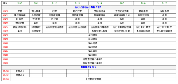
Figure 2 List of host ports
5. Main Circuit of the Variable Frequency Power Supply
The main circuit is depicted in Figure 3. The power supply can drive 10kV/4200kW or 6kV/4200kW motors and 3kV/2300V/1100V motors that are used for pump test. With the 10kV/4200kW motor as an example, set the rated output voltage of the power supply as 10 kV, set the over-current protection value and input parameters indicated on the tested pump motor's nameplate. If a pump motor that requires other voltage level is to be tested, one only needs to set the required output voltage and corresponding parameters.

Figure 3. Main Circuit of the High-voltage Variable Frequency Power Supply
6 External Ports
The entire variable frequency control device that includes control gear, power cabinet, transformer cabinet and bypass cabinet as well as all parts thereof and internal wirings are integrated; the user only needs to connect the high voltage output cable, high voltage input cable, control power source cable and control cable.
External ports are defined as below:
6.1 Switch Quantities from the Power Supply
The variable frequency power supply uses a PLC logic control panel developed by WindSun with its standard digital quantities configured as 24 outputs/16 inputs. I/O extension and parameter-based design are available if necessary. Other outputs are defined as below:
Power supply readiness indicator: means the power supply is ready; 1 channel; normally open point; closed state means readiness.
Power supply operation/shutdown indicator: means the power supply is operating or shut down; 1 channel for each. The operating state indicator is a normally open point, if closed, which means the power supply is operating; the shut-down state indicator is a normally closed point, if open, which means the power supply is shut down.
Power supply control state indicator: external control state is a normally open point, if closed, which means the power supply is remotely controlled; local control state is a normally closed point, if open, which means the power supply is locally controlled; 1 channel for each.
Power supply alarm indicator: means the power supply sends an alarm signal. These alarms include unauthorized cabinet opening, transformer over-temperature, power loss of control power source, disconnection of designated signal, unit failure and other information; 1 channel; normally open point; close means alarm.
Power supply failure indicator: means the power supply encounters a material failure, including over-voltage, over-current, over-load, short circuit and others, which will result in cut off of output and high voltage; 1 channel; normally open; close means failure.
Motor is at industrial frequency bypass: means the motor is bypassed at industrial frequency; normally open point; close means the motor is bypassed at industrial frequency.
Above are basic output state points of the variable frequency power supply.
6.2 Switch Quantities from Power Supply to High-voltage Switch-gear
High-voltage switch disconnection in emergency: In the case of material failure of power supply, the high-voltage switch is automatically disconnected; 1 channel normally open point; close means disconnection.
Permission for high-voltage switch connection: High-voltage switch is permitted to be connected; 1 channel normally open point; close means permission.
The above digit quantities are output by passive contacts and are valid when the contacts are closed. Unless otherwise specified, contact capacity is AC220V and 3A.
6.3 Switch Quantities from High Voltage Switchgear to Power Supply
High voltage readiness: It means high voltage is ready. 1 channel normally open point; close means readiness.
6.4 Analog Quantities from Power Supply
The power supply can provide 2 channels of 4~20 mA current source outputs and the load capacity of each channel is 250Ω. The two channels for output frequency and output current signals.
6.5 Switch Quantities from DCS to Power Supply
Start command: dry contact; valid when closed after 3-second pulses; the power supply starts operation.
Stop command: dry contact, valid when closed after 3-second pulses; the power supply stops in a normal manner.
Emergency stop command: dry contact, valid when closed; the power supply stops in an emergency.
6.6 Analog Quantities from DCS to Power Supply
The power supply provides 1 channel of 4~20 mA current power source input which can be customized, e.g., designated frequency, designated rotation speed, pressure feedback, as required to satisfy diverse needs.
6.7 Communication Protocol
The default communication protocol is MODBUS protocol with RS485 port. Communication protocol: PROFIBUS protocol, 2 communication ports, the power system and its onsite host form a redundancy system (the onsite host is Siemens SY-400 redundancy system).
7 The Effect of High-Voltage Variable Frequency Power Supply on Pump Test Stand
With WindSun power supply system, the upgraded system has been proved to function as expected. The WindSun power supply system operating on site is indicated in Figure 4. The test interface for 10 KV motor pump is shown in Figure 5. The apparent power, active power, input voltage, output voltage, input current, output current and output frequency of the high-voltage variable frequency power supply are 476 kW, 414 kW, 10.59 kV, 10.52 kV, 23.9A, 24.8 A and 50.00 Hz respectively. The test can be performed easily.
(1) All parts of the JD-BP38-7000 high voltage variable frequency power supply manufactured by WindSun Science & Technology Co., Ltd. are installed in the distribution cabinet, which means additional reactors, filters and other devices unnecessary. Low size, compact structure, easy for installation, less on-site wiring work, shortened commissioning period are obvious advantages of the power supply system.
(2) Operating parameters and all indicators of the power supply are displayed on the touch panel.
(3) The power supply has standard communication ports and can be totally integrated with the host computer through communication.
(4) The power supply can easily satisfy various pump test requirements by driving pumps that work at different voltage levels, such as 10kV/6kV/3kV/2300V/1100V, with an output current of up to 450A and 0-72Hz. What the user needs to do is to set the required parameters.
(5) With test performance that is comparable to that of exported systems, WindSun power supply system hugely lowers pump testing cost.

Figure 4 High-voltage variable frequency power supply that is operating on site
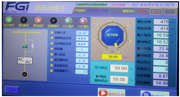
Figure 5 Human-machine interface of the high voltage variable frequency power supply
(6) Type test report of a pump tested with WindSun variable frequency power supply
Table 2 Pump type test report | ||||
Item | Product Name | Model/Specification | Test Category | Test Number |
Parameter | Middle-open pump | NSC400-300-570 | Type test | 151031 |
In the Test Center, pump flow, head, rotation speed, shaft power, efficiency and other performance parameters are tested. head (inlet head, outlet head and total head), power, rotation speed and efficiency at different flows are tested. As required, the power supply provides an output voltage of 10 kV, a stable loaded output, and satisfactory voltage, current and harmonics indicators, all of which meet the upgrading expectation. Figure 6 gives the type test report.
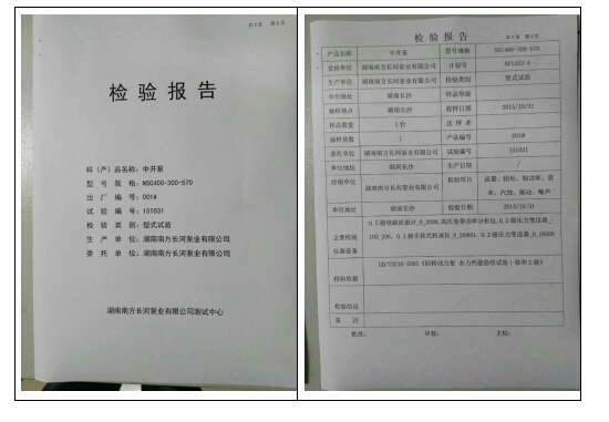 | 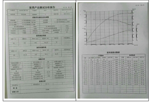 |
Figure 6 Type test report