Solution
Application ofHigh-voltage VFDs in a 300MW Thermal Power Plant
300MW circulating fluidized bed generation units in a thermal power plant in Hubei Province were put into production in November, 2009.The entire unit comprises circulating fluidized beds and natural circulation steam boilers with intermediate reheating produced by Dongfang Boiler Group Co., Ltd., which are installed in the open air, subcritical single shaft- steam turbines (model C300-16.67/1.0/537/537) with intermediate reheating and for exaction and condensation purposes produced by Dongfang Turbine Co., Ltd., and water-hydrogen cooling generators (model QFSN-330-2-20) produced by Dongfang Electric Machinery Co., Ltd, which are with self-excited shunt for static excitation.
The project was started on June 25, 2012 in an EPC mode, including electric control, mechanic work, civil building and HAVC work. This means seller is responsible for all supplies, installations and commissioning and delivering the completed project to owner after a 168-hour trial run free from any problem. The renovation project was constructed by WindSun Science & Technology Co., Ltd. which completed #1 unit renovation in October, 2012. The renovated #1 was successfully put into service immediately after the renovation and has been operating normally since then.
2、Parameters of Fans, Motors and Hydraulic Couplings on Site
Table 1 Parameters of fans, motors and hydraulic couplings on site | ||||
Name | Rated current | Rated speed | Power factor | Hydraulic model and parameter |
Induced draft fan | 243A | 994 | 0.87 | Y0T01150/3500kW/1000 r/min /3% |
Primary fan | 207A | 1493 | 0.87 | Y0T0875H/2900kW/1500 r/min /3% |
Figure 1 gives the performance curves of induced draft fans used in the 300MW generation unit. It is a centrifugal fan whose inlet guide blades adjust air flow. The 0°shown in Figure 1 means the adjusting door is fully opened and a negative angle means the adjusting door rotates toward the closing direction. Dash curves are iso-efficiency curves. A centrifugal fan reaches the peak efficiency when inlet adjusting door is fully opened, where its iso-efficiency curve is almost perpendicular to boiler resistance curve and efficiency drops rapidly along the resistance curve.
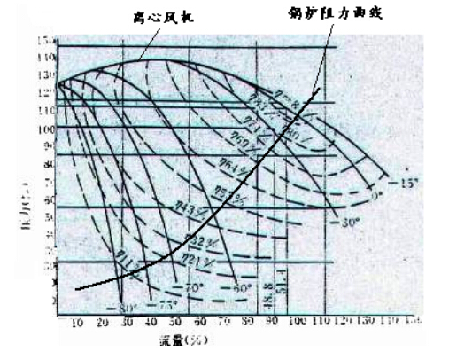
Figure 1 Induced draft fan’s performance curves
3 、How Fans Save Energy
Highlyefficient centrifugal fans are used as primary fans and induced draft fans in the unit, however, does not operate efficiently in fact. Two major reasons are their poor speed adjusting performance and operating point is far away from the highest efficiency point of fans. Air-flow margins for primary fans and induced draft fans used in thermal generation units are often around 5% and 7% and their air-pressure margins are around 10% and 13% because it is impossible to accurately calculate resistance of outlet pipes during design and problems that possible occur in actual operation must be considered. In this sense, system’s maximum air flow and air-flow margin are taken as the design values in fan model selection. Due to limited fan models and series, it is impossible to select the best suitable model in some cases where the only choice is to use a higher model. Thus, primary fans and induced draft fans have relatively higher air-flow and air-pressure margins.
Air-flow and air-pressure margins of fans for the unit and the unit’s operation in peak hours result in deviation of operating points of fans from their designed efficient points, which slashes operating efficiencies of fans. It should be noted that a large part of electricity consumed by primary fans and induced draft fans are attributed to adjusting doors due to mismatching fan models and piping system and improper adjusting methods. Thus, the most effective solution to increase fan efficiency and lower its electricity is to improve adjusting method of centrifugal fans.
According to the fluid machinery law, the relationship of flow Q, head H, shaft power P and speed n between a fan and a pump can be described as below:

When the speed of a centrifugal fan is being adjusted, if piping system resistance R is neglected and the square of air pressure H changes in proportion to air flow Q, it can be concluded that fan efficiency can be kept at the highest point within a certain range (the efficiency is only slightly lowered when actual load is less than 80% of the rated load). Figure 2 gives the electricity consumptions of a centrifugal fan when adjusted in different ways. Figure 3 gives a fan’s efficiency-air flow curves with air door adjustment and speed adjustment.
|
|
Figure 2 Figure 3
Figure 2 electricity consumptions of a centrifugal fan when adjusted in different ways
Figure 3 Fan efficiencies with two different adjusting methods
It can be seen from Figure 3 that when air flow declines from 100% to 50%, efficiency with variable frequency method is 30% higher than that with adjusting door on an average basis. To save energy, the best method is variable frequency adjustment. Fans are adjusted through air doors in the case of fixed speed drive. In addition to a large amount of electricity loss due throttling, slow response is also a major problem that results in combustor’s inability to be naturally started, which further prevents the unit’s coordinated control and unit’s inability to respond to dynamic load changes. VFD controlled fans improves unit’s controllability, speeds up its response and increases the control precision. This therefore greatly improves entire unit’s control performance, which not only gives rise to a better operation but also saves fuels considerably. Also, VFD can effectively reduce wear of blades and bearings, a way that extend useful life of equipment, lower noise and improves start performance. Better process conditions also mean better economic result.
4、Renovation Solution for Air-door Control to VFD Control
This project mainly involves installation, commissioning and operating of high voltage VFDs, through which, VFD’s onsite performance is verified. Two induced draft fans and two primary fans in #1 unit were to be upgraded. To ensure boiler system’s safe operation, VFDs which can be switched from industrial frequency to variable frequency automatically were adopted. Within 1 second after the switching, high voltage VFDs can be restarted, during which, the impulse surge is lower than 1.2 times of rated current. According to the operating data on induced draft fans and primary fans at industrial frequency provided by the user, these fans are not fully loaded. Even if the unit bears a load of 300M, motor current of induced draft fans at industrial frequency is only 160A, far smaller than 243A, the rated current; the motor current of primary fans at industrial frequency is about 120A, far smaller than 207A, the rated current. Given experience and for the purpose of lowering purchase cost, management of the thermal power plant decided to use 3000KW/10KV (JD-BP38) high voltage VFDs and 2200KV/10KV(JD-BP38) high voltage VFDs to drive induced draft fans and primary fans respectively.
High voltage VFD speed adjusting system has two monitoring modes available on site, i.e., local monitoring and remote monitoring. Under the first mode, VFDs can be manually started and stopped and its speed and frequency can be adjusted by operators by touch keyboard and buttons on VFDs and LCD/LED of the controller. Local control window is a Chinese operating interface where both function and parameter settings are made in Chinese. Under remote monitoring, an automatically control system (e.g., DCS) and a manual operation panel are available for easy operation; and real-time parameter display that covers VFD frequency and current, voltage and frequency of motor and start/stop fault display are provided.
High voltage VFD system is completed with self-diagnosis and protections against over-voltage, under-voltage, over-current, input inter-phase short-circuit, over-current, single-phase earthing, over-load, over-heating, IBGT breakdown or short circuit, unit failure, instantaneous outage together with shunt trip of incoming wiring switch at input side, in compliance with relevant national standards. VFDs can also provide over-load, over-current, over-voltage, under-voltage, heat accumulation and phase loss protections required by motors. In the event of any major fault in any part of a VFD, it can act immediately to prevent impact or damage to both grid and load.
4 VFDs were installed and commissioned for #1 boiler: one for induced draft fan A, one for induced draft B, one for primary fan A and one for primary fan B.
5 、Technical Parameters of WindSun JD-BP38 High Voltage VFD
With high speed DSPs as the core, JD-BP37/38 high-voltage VFDs produced by WindSun Science & Technology Co., Ltd. are designed with sensor-less vector, multi-level power unit series and other advanced control technologies. These are high-high voltage source VFDs, with harmonics much lower than the standard specified in IEEEE 519-2014. High input power factor and good output waveform save the use of input harmonic filter, power factor compensation device and output filter. They are free from problems caused by harmonics, e.g. additional heating and torque pulse, noise, common mode voltage and so on, and are suitable to conventional asynchronous motors. In September, 2007, WindSun JD-BP38 series was awarded with “China’s Famous Brand”.
Technical parameters for this series are listed in Table 2.
Table 2 Main technical parameters for JD-BP38-3000F high voltage VFDs | |||
VFD capacity(kW) | 3000 | Analog quantity input | Can be set within 0~5V/4~20mA |
Motor power(kW) | 3000 | Analog quantity output | Two optional channels 0~5V/4~20mA |
Rated output current(A) | 217 | Acceleration /deceleration time | 1~32000s |
frequency (Hz) | 45~55 | Switch quantity input/output | Can be extended as customer requires |
Rated input voltage (V) | 10000V(-20%~+15%) | Ambient temperature for operation | 0~40℃ |
Input power factor | >0.95(>20%负载) >0.95(>20%load) | Storage/transportation temperature | -40~70℃ |
VFD efficiency | >0.96 with rated load | Cooling method | Forced air cooling |
Output frequency (Hz) | 0~120 | Ambient humidity | <90%, no condensation |
Output frequency resolution (Hz) | 0.01 | Elevation | <1000m, downgraded for elevation higher than 1000m |
Over-load capacity | Continuous operation at 105% of rated load, 1 minute for 150% of rated load | IP grade | IP20 |
Technical parameters of JD-BP38-2200F high voltage VFDs are listed in Table 3
Table 3 Main technical parameters of JD-BP38-2200F high voltage VFDs | |||
capacity(kW) | 2200 | Analog quantity input | Can be set within 0~5V/4~20mA |
Motor power(kW) | 2200 | Analog quantity output | Two optional channels 0~5V/4~20mA |
Rated output current(A) | 159 | Acceleration /deceleration time | 1~32000s |
Input frequency (Hz) | 45~55 | Switch quantity input/output | Can be extended as customer requires |
Rated input voltage (V) | 10000V(-20%~+15%) | Ambient temperature for operation | 0~40℃ |
Input power factor | >0.95(>20%load) | Storage/transportation temperature | -40~70℃ |
VFD efficiency | >0.96 with rated load | Cooling method | Forced air cooling |
Output frequency (Hz) | 0~120 | Ambient humidity | <90%, no condensation |
Output frequency resolution (Hz) | 0.01 | Elevation | <1000m, downgraded for elevation higher than 1000m |
Over-load capacity | Continuous operation at 105% of rated load, 1 minute for 150% of rated load | IP grade | IP20 |
6、Main Circuit Introduction
Induced draft fans in #1 boiler used two JD-BP38-3000F VFDs (3000KW/10V) and primary fans in #1 boiler used two JD-BP38-2200F VFDs (2200KW/10KV) for speed control. The original hydraulic couplings were removed and motors moved forward. Couplings were used to directly connect motors to fans. The facility before renovation and after renovation are given in Figure 4 and Figure 5 respectively.
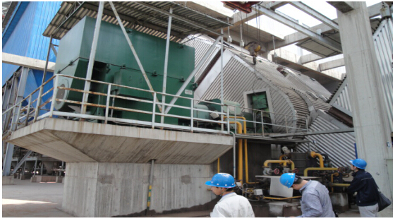
Figure 4 Before hydraulic couplings were removed 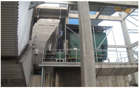
Figure 5 After hydraulic couplings were removed
Main circuit of induced draft fans and primary fans is given in Figure 6.
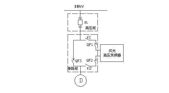
Figure 6 Diagram of bypass cabinet for induced draft fans and primary fans
Induced draft fans and primary fans in #1 boiler were operating at industrial frequency before renovation. Four VFDs were added to the four fans and can be automatically bypassed in the event of failure. Original air door adjustment was changed to VFD adjustment. In the case of VFD failure or service, fans can be switched to industrial frequency automatically. Under variable frequency mode, one can adjust fan frequency on DCS interface to change fan speed, thereby adjusting air flow.
To ensure safe operation of the generation unit, power system of fans can be automatically bypassed. Under automatic bypass mode, if the VFD fails and automatic bypass on is allowed, high voltage input and output switches of VFD are switched off, after a delay, industrial frequency bypass switch is switched on, which makes the motor start at industrial frequency ; at the same time, DCS logic changes air flow adjusting method to industrial frequency adjusting. In this case, operators play a role in the adjustment to keep normal air flow and air pressure, ensuring combustion chamber work normally.
After VFD repair is completed and the system is going to operate in VFD mode, outlet dampers of induced draft fans can be closed such that a single VFD drives 50%~70% of boiler load; then, fans are switched to variable frequency mode. With the flying start mode provided by the VFD, system will be recovered when fans are not fully stopped, a way that can significantly reduce the time that the unit takes to decrease its load.
The main circuit is shown in Figure 6. In the bypass cabinet, two isolator switches are added to the incoming and outgoing terminals of the VFD such that when the motor is working in bypass mode it is possible to safely repair or maintain VFD.
Bypass cabinet has three vacuum breakers (QF1, QF2 and QF3) and two isolator switches (K1 and K2). QF2 and QF3 provide electric interlock. When QF1 and QF2 are closed and QF3 is open, the motor works at variable frequency mode. When QF1 and QF2 are open and Q3 is closed, the motor works in industrial frequency mode. When QF1 is closed, K1 lever is locked. When QF2 is closed, K2 lever is locked.
If VFD is to be repaired or maintained when the motor is working at industrial frequency, it is important to disconnect K1 and K2 when QF1 and QF2 are switched off.
Switch on: “Switch on permitted” signal of the VFD is connected to QF1 and QF2 circuit in series. In cases where VFD fails or is not ready, it is not allowed to switch on QF1 and QF2. If VFD fails when QF1 and QF2 are switched on, the “switch on permitted” signal is disconnected, casing trip of QF1 and QF2; in this case, input power supply for the VFD is disconnected.
Automatic bypass process for transformation from variable frequency to industrial frequency: “Bypass on” signal of VFD is connected to QF3 circuit in parallel. In variable frequency mode, if the VFD fails and automatic bypass on is allowed, high voltage input and output switches, QF1 and QF2, of VFD are switched off, after a delay, “bypass on” is closed, i.e., QF3 is switched on, which makes the motor start at industrial frequency and bypass state signal is sent to DCS, which changes air flow adjusting method to industrial frequency adjusting.
If any VFD risk is detected, VFD sends “VFD alarm” signal to DCS; at this time, VFD continues working and service staff removes the risk based on the alarm.
7 、Renovation Effect
7.1 Energy saving calculation
Variable frequency renovation project on fans for #1 boiler in the Hubei thermal power plant was successfully completed and put into production, providing expected result. High voltage VFDs that are operating on site are shown in Figure 7.
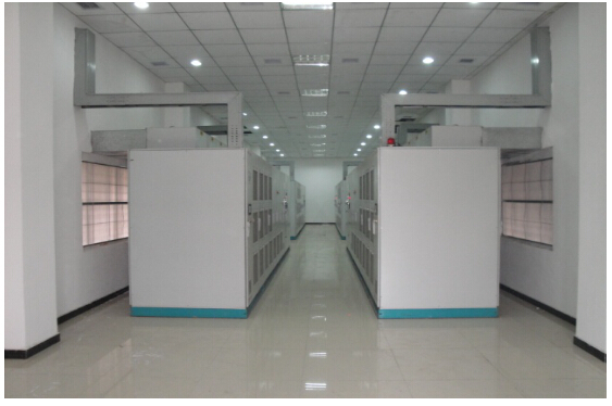
Figure 7 High voltage VFDs are operating on site.
Production data of #1 unit with different loads before and after the renovation project on 2 induced draft fans and 2 primary fans are given in Table 4 to Table 8.
7.1.1Operating data of induced draft fans in industrial frequency and variable frequency modes
(1)Operating parameters of induced draft fans in industrial frequency mode (air door dampers are fully opened)
Table 4 Operating parameters of induced draft fans in industrial frequency mode | |||||
Load | Fan A | Fan B | Probability | ||
Current (A) | (r/min) | Current (A) | (r/min) | ||
230MW | 109 | 516 | 110 | 529 | 25% |
250MW | 111 | 568 | 111 | 574 | 35% |
280MW | 139 | 642 | 143 | 672 | 30% |
300MW | 160 | 725 | 163 | 752 | 10% |
(2)Operating parameters of induced draft fans in variable frequency mode (air door dampers are fully opened)
Table 5 Operating parameters of induced draft fans in variable frequency mode | |||||
Load | Fan A | Fan B | Probability | ||
Current (A) | Frequency (Hz) | Current (A) | Frequency (Hz) | ||
230MW | 62.5 | 39.26 | 57.8 | 39.88 | 35% |
250MW | 64.1 | 39.77 | 56.4 | 37.87 | 45% |
280MW | 86.1 | 42.08 | 89.2 | 43.9 | 20% |
7.1.2 Operating data of primary fans in industrial frequency and variable frequency modes
(1) Operating parameters of primary fans in industrial frequency mode (air door dampers are fully opened)
Table 6 Operating parameters of primary fans in industrial frequency mode | |||||
Load | Fan A | Fan B | Probability | ||
电流Current (A) | Speed (r/min) | 电流Current (A) | Speed (r/min) | ||
230MW | 110 | 1059 | 111 | 1037 | 25% |
250MW | 111 | 1049 | 111 | 1022 | 35% |
280MW | 112 | 1052 | 113 | 1018 | 30% |
300MW | 117 | 1074 | 113 | 1013 | 10% |
(2) Operating parameters of primary fans in variable frequency mode (air door dampers are fully opened)
Table 7 Operating parameters of primary fans in variable frequency mode | |||||
Load | Fan A | Fan B | Probability | ||
Current (A) | Frequency (Hz) | Current (A) | Frequency (Hz) | ||
230MW | 88.5 | 32.43 | 88.7 | 32.81 | 35% |
250MW | 98.2 | 36.4 | 96.3 | 35.44 | 45% |
280MW | 100.1 | 37.61 | 98.1 | 36.71 | 20% |
Direct economic benefit (base on electricity price ¥0.478/KWh)
Table 8 Energy saving calculation | ||||
序号 No. | Device name | Electricity saved per year (8000h) per device (KWH) | Electricity bill saved per year per device (¥10,000) | Total electricity bill saved per year (¥10,000) |
1 | 2 x induced draft fan (3000kw) | 217.2 | 103.8 | 207.6 |
2 | 2 x primary fans (2200KW) | 187.8 | 89.8 | 179.6 |
Total | 387.2 | |||
The project employed 4 high voltage VFDs for induced draft fans and primary fans. Under variable frequency mode, 2,172,000 kW•h can be saved per year per induced draft fan and 1,878,000 kW•h per year per primary fan. Assuming electricity price is ¥0.478/kW•h, the four VFDs can save ¥ 3, 872,000.00 per year.
7.2 Other effects
(1) With VFDs, motors are able to start softly, eliminating the impacts on grid and loads, avoiding motor insulation damage due to over-voltage and extending the useful lives of motors and fans.
(2) Variable frequency mode reduces throttling loss and adjust speeds continuously for meeting production needs and saving electricity.
(3) Speed can be lowered if the load becomes smaller, which can reduce mechanical wear and vibration, extend overhaul cycle and saves a large amount of overhaul expense.
(4) High control precision, strong interference immunity, small harmonic component and complete protections are good for safe operation of motors and fans.
8 Conclusion
WindSun JD-BP38 high voltage VFDs are successfully applied to fans in #1 unit in the Hubei thermal power plant. Many industrial applications have proved that high voltage VFDs are both powerful and reliable. Promoting the use of high voltage VFDs in many high voltage and large power fans and pumps can considerably save energy and receive policy supports.