Solution
V/F Control-based VFD for Multi-motor Belt Conveyors
1 Introduction
In many cases, a large power VFD is used to drive multiple motors that tract a belt conveyor. Despite that all motors receive the same frequency outputted by VFD, output torques from all motors vary due to cylinder size, belt angle and other factors, which result in different output powers. This problem shortens useful lives of motors and belts, restricting wide application of VFD in multi-motor driven belt convertor systems.
When a multi-motor driven belt conveyor system is starting, operating or preparing to stop, improper control (if any) will cause output torques of motors vary from one another, even different motor states, which means, for example, some motors are consuming electricity and others are generating electricity. This case is fatal to VFDs, which often uses diodes as uncontrolled rectifier. In an uncontrolled rectifier, a motor that is generating electricity will charge the capacitor through IGBT’s flyback diode. Since the capacitor uses diodes for rectifying purpose, a way that energy flow cannot be reversed, such that the capacitor’s voltage will be increased until the unit’s over-voltage protection works. To this end, a proper control method that can keeps consistent the output torques of all motors when the system is starting, operating or preparing to stop critical for multi-motor belt conveyor system driven by a V/F control-based VFD.
2 Technical Principle and Implementation
2.1 VFD’s basic principle and structure
A VFD is a converter that changes the constant voltage and constant frequency supplied by grid to an adjustable voltage and adjustable frequency, giving better play to motors driven by power supplies with variable voltage. In a word, voltage and frequency output by a VFD are adjustable. In this way, A VFD makes soft starting and frequency and speed adjustment possible for AC asynchronous motors, improves their precision and changes their power factors.
The asynchronous motors and VFD mentioned in the present work are high voltage devices, often at 6kV and 10kV. The latter is cascaded voltage-source type high voltage VFD, whose structure and working principle are described as below.
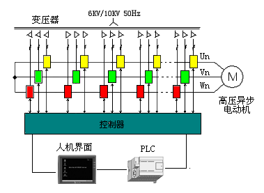
Figure 1 Structure of a Cascaded High Voltage VFD
As shown in Figure 1, main circuit of the cascaded high voltage VFD comprises a phase-shifting transformer, power units, a main controller and an electrical control system. The grid inputs a 10kV or 6kv three-phase voltage, which through the phase-shifting transformer, becomes n low-voltage, independent and phase-shifted secondary winding power supplies, which are connected to power units one by one. Then, through rectifier, filter and inverter, these power supplies become a single-phase AC power supply, outputted by power units. If the input voltage is 6kV, each phase is a series of 5 power units, each of whose maximum output power is 759V, which means the maximum output phase voltage is 3796V and the maximum output line voltage is 6572V. When the VFD is fully loaded, excluding voltage drops due to transformer and power units, the actual output is about 92% of maximum output. The phase-shifting transformer’s role in multiplexing current can lower harmonic current at grid side. With different connections, 5 secondary windings make the current difference between primary and secondary windings is 12°. At primary side of the transformer, a 30-pulse rectifier circuit is formed, theoretically, which can eliminate harmonics of lower than 29th order at grid side.
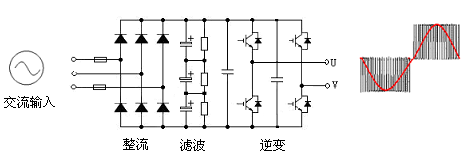
Figure 2 Basic Structure of a Power Unit
Power units in series spares voltage imbalance problem. Each power unit bears total output current and only 1/5 of output phase voltage and 1/15 of output power. This structure makes the input power factor exceed 0.95. Although this main circuit topology uses more components, much lower IGBT drive power and the elimination of voltage balancing circuit, absorption circuit and output filter circuit increase VFD’s efficiency to be higher than 96%.
As indicated in Figure 2, a power unit is a low-voltage PWM voltage type inverter that consists of 4 low voltage Insulate-Gate Bipolar Transistors (IGBT), being able to output three states, i.e., 1,0 and -1. Each phase is the superimposition of 5 power units. Use of multiplex SVPWM technology can produce 11 different potential levels, forming a phase voltage of an 11-level square waveform and a line voltage of a 21-level square waveform. The output waveform approximates to sine wave and has a small harmonic component.
5 power units are superimposed to form a phcase of the three-phase 6KV cascaded multi-level VFD in such a way as indicated in Figure 3 (take one phase as an example).
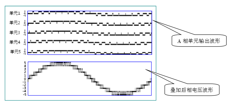
Fig.3 The phase voltage waveform of cascade multilevel inverter
Each phase outputs an 11-level square waveform.
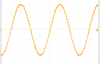
Figure 4 The Line Voltage Waveform of Cascaded Multi-level VFD
2.2 Speed Adjustment and V/F Control Principle
When a stator winding in a motor is energized by a three-phase AC supply, a rotating magnetic field will be produced in the air gap between stator and rotor and moves in relative to rotor winding. This relative movement causes rotor winding to produce an inductive potential which generates an inductive current, whose interaction with the rotating magnetic field produces an electromagnetic torque, making the motor rotate. This magnetic field’s rotation speed is called a synchronous rotation speed and denoted with N:
N = 60×f/p(r/min) (1)
Where: f—three-phase supply’s frequency, often 50Hz;
P—number of pole pairs. When P=1, N=3000 r/min; when P=2, N=1500 r/min. This indicates the larger P, the smaller N. Actual rotor speed n is slower than the synchrotrons speed N. This makes this motor called an asynchronous motor. The speed difference is denoted with s:
s = [(N-n)/N]×100% (2)
At the moment when the power supply is connected but the rotor has not started, n=0, which means s=1. In an extreme case after rotor starts, n=N, which means s=0. Therefore, s changes between 0 and 1. Generally, the s for an asynchronous motor with rated load is between 1% and 6%.
The following can be attained from equation (1) and equation (2)
n = 60×f×(1-s)/p (3)
It can be seen from equation (3) that since P is given for an asynchronous motor and s does not change too much, motor speed n is proportional to power supply frequency f. This means that it is possible to change synchrotrons speed by changing power supply’s frequency, thereby adjusting the asynchronous motor’s speed.
The main flux must be maintained to the largest extent when an asynchronous motor’s speed is being changed because: 1) with the same rotor current, iron core is not made the most use of if the flux is too weak, which results in a small electromagnetic torque and reduces motor’s load capacity; 2) iron core is excessively excited if the flux is too strong, producing an excessive exciting current, which restricts stator current’s load component and reduces motor’s load capacity.

Figure 5 Principle Diagram for a V/F Control-based VFD System
In this sense, efforts are made to keep the main flux at its rated value. Thus, in an asynchronous motor, the absolute value of electromotive force for each stator phase is:(4)
Where:
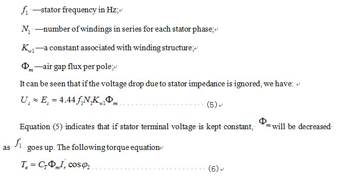
indicates that when is kept constant, decrease results in decline of motor’s output torque, and even causing the motor to stall. Therefore, it is required to change stator voltage and frequency when one is trying to adjust motor speed, a way to maintain the main flux. This is basis of V/F control. As depicted in Figure 5, is the give frequency, which is then subject to acceleration/declaration, becomes, the output frequency. Next, an output voltage U is obtained in V/F control mode, and subject to SVPWM, becomes a three-phase SVPWM wave, which drives a voltage source type inverter, whose output is sent to the asynchronous motor to which it connects.
2.3 Structure and principle of the master/slave control system
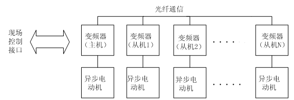
Figure.6 The Schematic Diagram of Multi-Motor Belt Conveyor System
Figure 6 outlines the principle of a V/F control system for a multi-motor driven belt conveyor. AC asynchronous motors, identical in specification, are used to drive the belt conveyor. Each asynchronous motor is driven by a VFD. Among these VFDs, only one is the master and all others are salves. Master VFD provides communication with host. For each VFD, its power supply input terminal is connected to grid and output terminal connected to input terminal of stator in the motor to which it drives. Master VFD and slave VFDs communicate via fiber optic cables. VFDs detect active currents and adjust their operating frequencies to balance powers of all motors.
VFDs in Figure 6 are voltage source cascaded high voltage ones. V/F control is used in the multi-motor driven belt conveyor system. Under this control mode, stator windings in the system are energized by a voltage determined by a preset V/F curve. This voltage’s characteristics are equivalent to a stable AC voltage source and its stability is close to an industrial frequency grid. Compared with other control modes and other VFDs, V/F control-based VFD presents higher stability and reliability. What is more, reactive currents of all motors in the system only flow between stator windings and VFDs instead of flowing into grid; this lowers the requirement for grid capacity and increases system’s input power factor.
In Figure 6, each VFD collects a three-phase output current, Ia, Ib and Ic, through its own current sensor. Ia, Ib and Ic in a three-phase static reference system is first transformed into α and β in a two-phase static reference system (Clarke transformation or 3/2 transformation), which is then transformed into a synchronously rotating reference framework (Park transformation), for which, the synchronous angle is output voltage vector angle of the VFD. In this way, the direct current Iq and Id in an equivalent synchronously rotating reference framework is obtained. Id is the exciting current, also known as reactive current, often being 30% of motor’s rated current; Iq is an armature current in proportion to motor torque, also known as active current. By controlling active current, one can control active power outputted by a VFD, and ultimately keeping torques and powers outputted by all motors consistent.
2.4 Specific implementation
V/F controlled VFD for multi-motor driven belt conveyor system employs master/slave control. Each motor in the system is driven by a VFD. Among all VFDs, only one is the master and all the other are slaves. In this paper, a solution is proposed to solve critical problems relating to multi-motor driven belt conveyor system, such as variable-frequency based start, stop, operation adjustment and failure protection. This solution is a V/F control-based VFD for multi-motor driven belt conveyor systems, which makes it possible to change speeds through variable frequency drive in this application.
The control processes used in the V/F control-based VFD for multi-motor driven belt conveyors, including start process, operating process and stop process, are depicted in Figure 7 and Figure 8. Figure 7 shows the process for master VFD and Figure 8 for slave VFD.
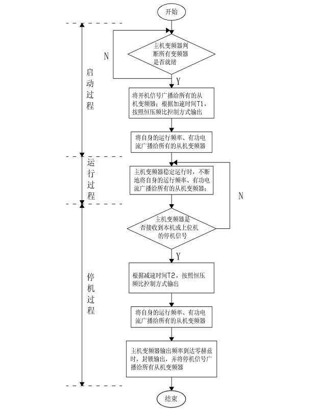
Figure 7. Master VFD’s Flow Chart
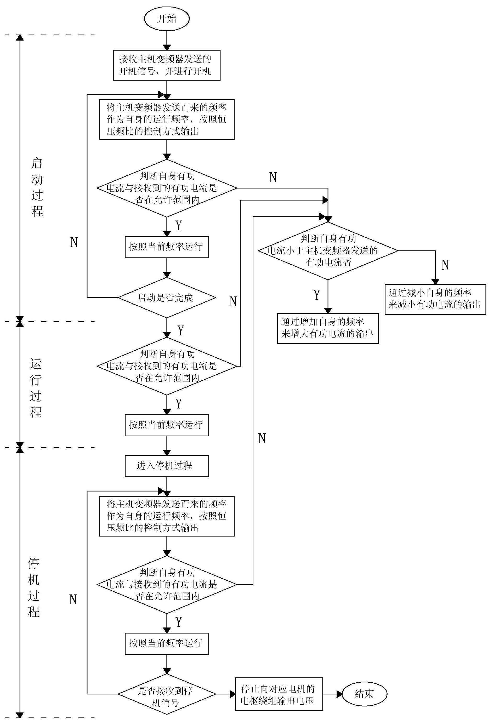
Figure 8 Slave VFD’s Flow Chart
Master VFD and slave VFDs are connected through fiber optic cables, a way can improve transmission speed to speed up response and provide electric isolation for reducing external interference.
After receiving a local or remote start/stop command, master VFD will broadcast the command to all slaves after it confirms all VFDs are ready and free from failure. This means slaves are controlled by master in terms of start/stop.
After getting started, master VFD increases or decreases frequency for the preset acceleration time and declaration time and broadcast’s its own operating frequency to all slave VFDs, which, after receiving the benchmark frequency from master, adjust their own frequencies to benchmark frequency.
At the same time, master VFD detects its own output active current and broadcast it as the benchmark to all slave VFDs, which, after receiving the benchmark, compare their own currents with the benchmark, and increase their frequencies benchmark is higher or decrease their frequencies if benchmark is lower. A belt conveyor is constant torque system, which requires a fixed total torque. Decline of a VFD’s output frequency will result in decrease of output active current, decrease of output torque by the motor it drives, and increase of output torques of other motors. It is like two horses driving a wagon, the faster one consumes more energy and the slower one less. The faster one must slow down and the slower one speed up in order to balance their energies. The ultimate goal for a slave VFD to adjust its output frequency is to keep its own active current consistent with the benchmark current sent from master VFD. This ensures all motors output the same torque and the same power.
While broadcasting signals, master VFD receives feedback signals from slave VFDs to determine communication and real-time operation of slave VFDs. If any master/slave communication failure, any failure of grid relating to master or salve VFDs, or major failure inside master or slave VFDs, or motor failure is found, master VFD immediately locks its output and stops, and broadcasts the stop command to all salve VFDs through fiber optic cables.
The idea behind this control is to drive a multi-motor belt conveyor by using V/F control-based VFD system in order to have the conveyor start and stop smoothly and operate efficiently; in the case of emergency, motors and VFDs can be protected reliably. This solution has extended the applicability of V/F control-based VFDs, increased speed adjusting options available to multi-motor belt conveyor systems and lowered the cost of upgrading multi-motor belt conveyor system into a variable frequency control system. Due to V/F open loop method, this solution spares the use of speed and location sensors and the necessity of detecting motor parameters, thereby improving motor reliability and stability and lowering system failure rate.
3 Experiment
The afore-mentioned technical solution is proved to be feasible after product verification and has received technical test and evaluation.
For example, in a two-motor belt conveyor system installed in a coal washery in Shanxi Province, each motor, whose rated power is 560kW and rated voltage is 10kV, is driven by an individual VFD. With the control solution mentioned previously, the system can start and stop smoothly and operate efficiency in a variable frequency manner. The basic operating parameters are in the following table.
Table 1 Operating Parameters of Master and Slave VFDs
Operating parameter | Master VFD | Slave VFD |
Input voltage | 10.02kV | 10.03kV |
Output voltage | 9.78kV | 9.76kV |
Input current | 22.4A | 22.4A |
Output current | 28.9A | 29.3A |
Output active current | 26.1A | 26.5A |
Given frequency | 49.00Hz | 49.00Hz |
Operating frequency | 48.83Hz | 48.67Hz |
It can be seen from above table that output frequencies of two VFDs are 48.83 Hz and 48.67 Hz respectively, output currents are 28.9A and 29.3 A respectively, output active currents are 26.1 A and 26.5 A respectively, indicating master and slave VFDs basically share the same operating frequency and the same operant current. This guarantees balanced powers of two motors and helps extend service life of the belt system.
4 Conclusion
In this paper, VFD structure and principle, speed adjusting and V/F control principle for VFDs and how to drive multi-motor belt conveyors by using V/F controlled VFDs are detailed. The way in which V/F control works, the principle of master/salve control and the processes for a multi-motor driven belt conveyor system to start, stop and operate are described. V/F control-based VFDs are proved to be useful in a practical multi-motor driven belt conveyor.
V/F Control-based VFD for Multi-motor Belt Conveyors